AMASC01 Installation Guide
This guide provides complete step-by-step instructions for installing and setting up the AMASC01 AllSky camera.
Due to various installation configurations and mounting options, mounting hardware and accessories are not included with the camera. Installation kits and PoE injectors are available upon request. Please contact us if you need these components.
Pre-Installation Checklist
Before beginning installation, ensure you have:
- PoE-capable Ethernet switch or PoE injector (IEEE 802.3af/at)
- Ethernet cable of appropriate length
- Stable mounting structure with unobstructed sky view
- Tools for mounting (depending on your specific mount)
- Computer or device for initial configuration
- Network scanner or access to DHCP server logs (for finding camera IP)
Step 1: Mounting
Location Selection
Choose an installation location that provides:
- Unobstructed sky view – 180° clear view in all directions
- Stable support structure – pole mount, roof mount, or dedicated stand
- Protection from direct sunlight – avoid locations where sun shines directly on dome
- Accessibility – easy access for maintenance and cleaning
- Weather consideration – protected from extreme wind loads if possible
Physical Mounting
The preferred and recommended mounting method uses a pair of 80 mm diameter two-bolt clamps with rubber inserts to secure the camera to a tube or pole. This mounting system provides excellent stability.
Option 1: Vertical Pole Mounting (Recommended)
This is the recommended mounting configuration for most installations.
- Attach first clamp to camera mounting bracket
- Connect to support pole using:
- Two threaded rods (M8 2× 150 mm length)
- Second set of clamps sized for your support pole diameter
- Position the camera at desired height on vertical pole
- Ensure the camera is level – use level for optimal sky coverage
- Tighten all bolts firmly but avoid over-tightening
- Verify stability – camera should not move in moderate wind
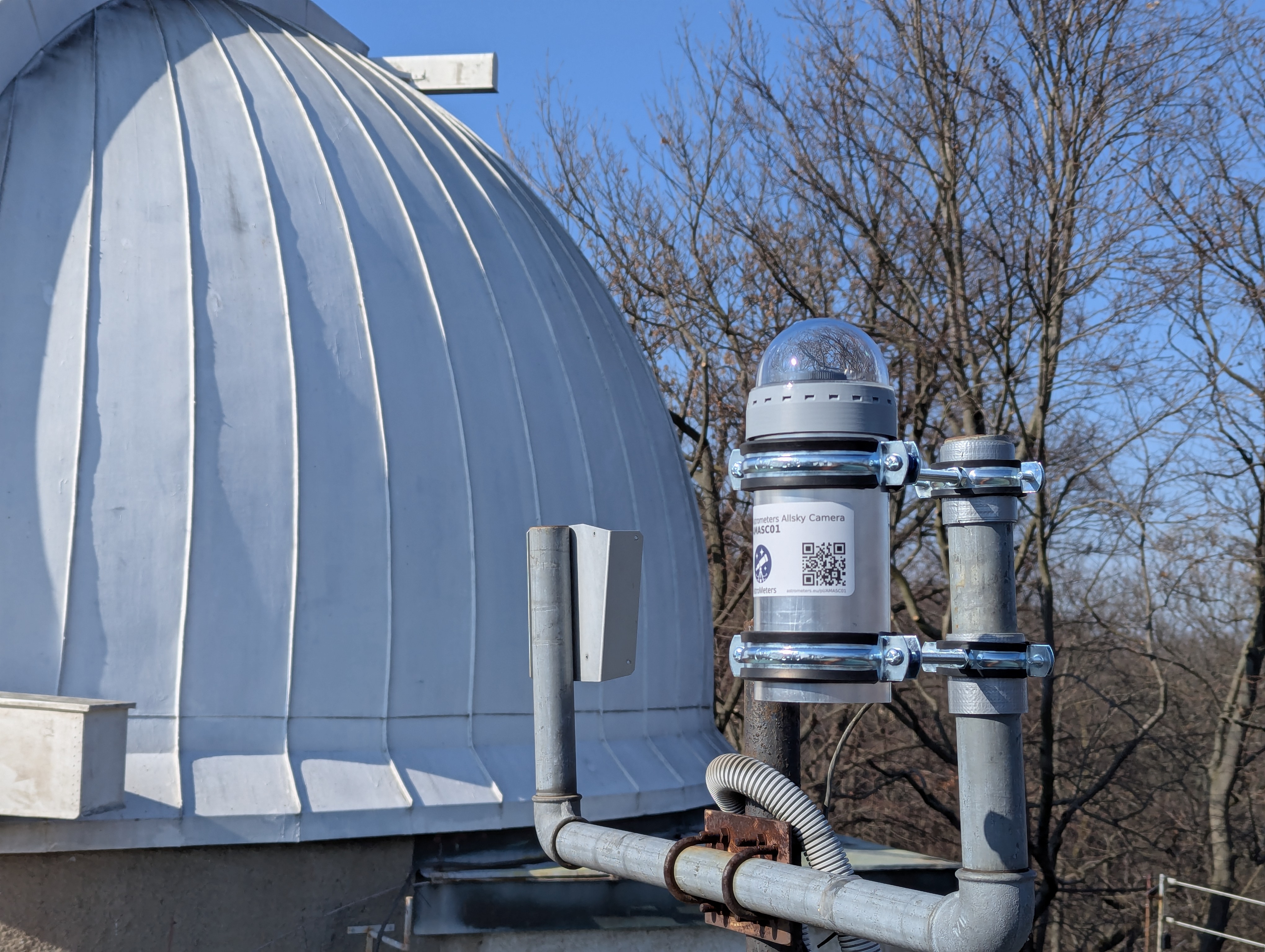
Example of a possible AMASC01 installation using clamps mounted to a vertical pole.
Option 2: Wooden Beam/Structure Mounting
For mounting to wooden beams, rafters, or timber structures:
- Select mounting points on wooden beam (ensure beam is structurally sound)
- Use lag screws with metric thread (combo screws):
- Wood screw thread on one end
- Metric thread on other end for clamp attachment
- Drill pilot holes in wooden beam (appropriate diameter for wood screw)
- Screw lag screws into wooden beam until metric thread protrudes
- Attach camera clamp onto metric threads
- Ensure the camera is level – adjust clamp position if needed
- Verify stability – camera should be firmly secured
Use appropriate length lag screws to ensure adequate penetration into wood (minimum 50-60 mm into beam)
Option 3: Custom Mounting Solutions
For specialized installations (roof mounts, wall brackets, etc.), it is still strongly recommended to use the 80 mm rubber-padded tube clamps to attach the camera to your custom mounting bracket. This provides secure attachment, which is beneficial for image quality.
- Ensure mounting surface can support camera weight plus wind loads
- Use appropriate hardware for your specific mounting surface
- Maintain 80 mm clamp interface for camera attachment
- Ensure camera can be leveled and adjusted
- Verify all connections are weather-resistant
Final Mounting Checks
Regardless of mounting method:
- Allow clearance at the bottom for cable connection and ventilation
- Verify stability – camera should not move in moderate wind
- Check level – dome should be horizontal for optimal sky coverage
- Test adjustability – ensure you can access focus and orientation adjustments
- Inspect all fasteners – confirm everything is secure
Cable Management
- Route Ethernet cable from camera to network connection point
- Secure cable to fixed structure as soon as possible – cable must be firmly attached to prevent movement
- Protect cable from weather exposure using conduit or cable tray
- Create drip loop below connection point to prevent water ingress
- Leave some slack for camera adjustments and maintenance
Important: Cable must be properly secured to prevent damage from weather conditions. Forming ice, snow load, or wind can put significant stress on the cable, potentially tearing it loose and damaging the camera. Careful cable securing is critical for long-term reliability.
Step 2: Power & Network Connection
PoE Connection
- Connect Ethernet cable to camera’s RJ45 port
- Connect other end to PoE switch or PoE injector
- Verify PoE power – ensure switch/injector provides sufficient power (IEEE 802.3af/at)
- Check power indicator – one LED on the bottom side of the camera will illuminate approximately 3 seconds after power connection
- Camera will boot automatically when power is applied (takes ~1-2 minutes)
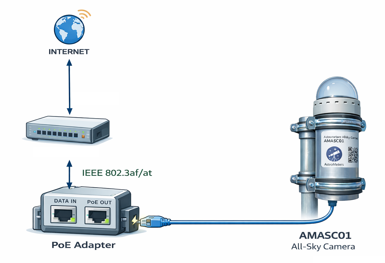
Example wiring diagram showing AMASC01 connection through a PoE injector / adapter.
Verify Network Connection
- Check link LED on PoE switch/injector (if available)
- Wait for boot – camera needs time to initialize
- Check camera network activity – the middle LED indicator shows network port activity. This LED will only illuminate when the camera is fully booted and connected to an active switch or other network device, confirming the camera is communicating over the network
- Locate camera IP address:
- Default hostname:
astrometers-allsky – in home networks, you can try to access the camera directly at http://astrometers-allsky
- Check DHCP server logs
- Use network scanner (e.g.,
nmap, arp-scan)
- Check your router’s connected devices list
- For institutional networks: Contact your network administrator to locate the camera’s assigned IP address
Note: The hostname-based access (http://astrometers-allsky, http://astrometers-allsky.local, http://astrometers-allsky.lan) typically works in home networks. In institutional or enterprise networks, hostname resolution may not be available, and you will need to use the IP address directly.
Step 3: Initial Web Interface Access
First Connection
- Open web browser on a computer connected to same network
- Navigate to camera IP:
http://[camera-ip]
- Login with default credentials (admin/secret)
- Verify camera is functioning – you should see live preview
Network Configuration (Optional)
If you need to set a static IP address:
- Navigate to network settings in web interface
- Change from DHCP to static IP
- Configure IP address, subnet mask, gateway
- Apply changes and reconnect using new IP
Step 4: Focusing
The AMASC01 features an accessible precision focusing mechanism that can be adjusted without disassembling the camera.
Focus Adjustment Procedure
- Access focus adjustment ring – located on the lens assembly
- Loosen lock ring if present
- Initial focusing – if the camera is significantly out of focus, perform initial focusing during daytime on distant terrestrial objects
- Fine-tuning – for optimal focus, adjust at night using bright stars (Sirius, Vega, etc.) as reference. Stars should appear as sharp points, not circles
Note: Check focus across the entire frame (edges and center). Make small adjustments – they make significant differences in image quality.
Step 5: Initial Configuration
Basic Imaging Parameters
- Exposure settings:
- Start with recommended defaults
- Adjust based on light pollution levels
- Night images typically 10-30 seconds
- Day images 0.001-0.01 seconds
- Gain settings:
- Lower gain for dark skies (less noise)
- Higher gain for light-polluted areas (if needed)
- Image format:
- Choose resolution and file format
- Configure compression if needed
Image Masking
Configure masking to exclude unwanted areas:
- Navigate to mask editor in web interface
- Draw masks over:
- Tree branches or buildings
- Light sources at horizon
- Other obstructions
- Save mask configuration
Configure information overlays:
- Select overlay elements:
- Timestamp
- Camera name/location
- Temperature, humidity, pressure
- Exposure settings
- Star map/constellation lines (if available)
- Position overlays on image
- Choose font size and color
- Save overlay configuration
Archiving and Storage
Configure image archiving:
- Set archive location (local storage or network)
- Configure retention policy (how long to keep images)
- Enable time-lapse generation if desired
- Configure upload to external services (optional)
Step 6: Hardware Control Configuration
Hardware control settings (dome heating, ventilation, anti-dew) are pre-configured from factory with optimal default values. You can verify and adjust these settings if needed for your specific environmental conditions.
Maintenance Schedule
Seasonally
- Clean dome and enclosure
- Review dome condition (fogging, dirt)
- Verify heating/ventilation operation
- Inspect mounting hardware
- Verify focus (refocus if needed)
- Check firmware updates
Troubleshooting
For common issues and solutions, see the FAQ page.