We use cookies on this site to enhance your user experience
By clicking the Accept button, you agree to us doing so. More info on our cookie policy
We use cookies on this site to enhance your user experience
By clicking the Accept button, you agree to us doing so. More info on our cookie policy
Dome heating, ventilation and environmental monitoring of the AMASC01
The thermal control daemon keeps the AMASC01 camera dry and cool during long-term outdoor operation:
It runs as the thermal-control systemd service and is controlled with the thermal-control-cli command.
The hardware it drives is described in AMRPI4HAT01 carrier board; the source code is open and available in the
AMASC01 repository.
All thermal control settings are pre-configured from the factory with defaults suitable for most environmental conditions. Advanced users can adjust them for specific deployment scenarios.
Log in to the camera over SSH and run:
thermal-control-cli --help           # list of all commands
thermal-control-cli test --help      # options of a command
python3 /opt/amasc01/current/camera_supervisor/thermal_control.py --help   # daemon configuration options
thermal-control-cli status           # current readings and outputs
thermal-control-cli test             # interactive hardware test (fans, sensors, heater)
journalctl -u thermal-control -f     # live log
The daemon --help shows the built-in defaults; the running service uses the values from the systemd unit and
/amasc01.env, see Configuration.
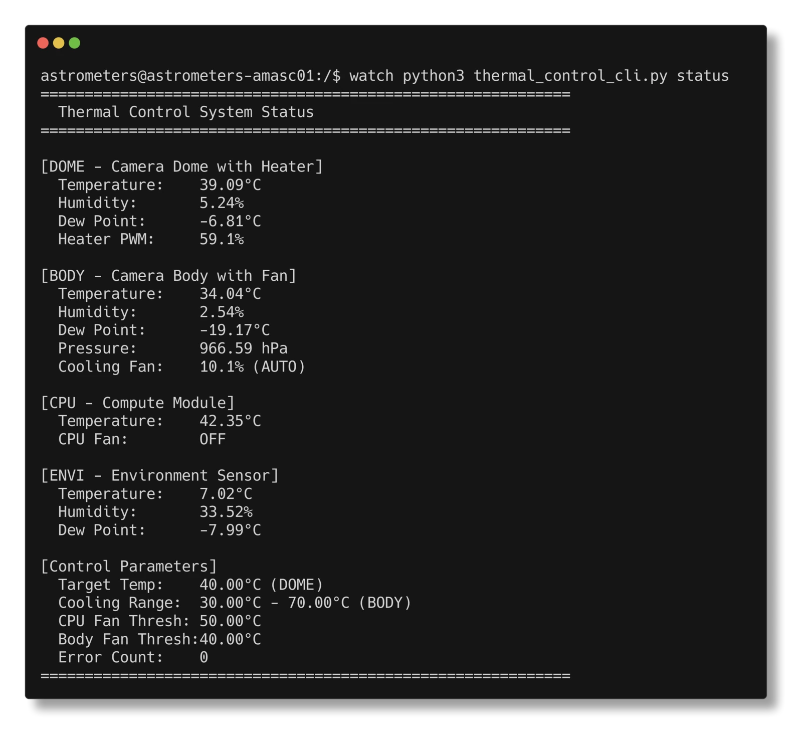
Thermal control status view in the terminal.
After a new installation set the board variant in /amasc01.env (see Configuration) and
restart the service.
| Name | Chip | I²C bus / address | Location | Used for |
|---|---|---|---|---|
| DOME | SHT40 | bus 10 / 0x44 |
at the optical dome | heater control (PID) |
| BODY | BME280 | bus 1 / 0x76 |
on the AMRPI4HAT01 board, inside the camera body | body fan control, pressure |
| ENVI | SHT41 | bus 1 / 0x44 |
on the AMHATLED01 board, at the air intake | monitoring only |
| CPU | – | /sys/class/thermal/thermal_zone0/temp |
Raspberry Pi SoC | CPU fan control |
For DOME, BODY and ENVI the daemon also computes the dew point (Magnus formula). Readings outside −20 °C … 70 °C are treated as failed reads.
Note: The ENVI sensor does not replace a weather station. It measures the temperature and humidity of the air at the camera’s air intake, and the reading is influenced by the camera casing (sunlight, heat from the camera body).
| Output | Driven by | Control |
|---|---|---|
| Heater | hardware PWM (50 Hz) | PID on DOME temperature |
| Body fan | hardware PWM (50 Hz) | linear on BODY temperature |
| CPU fan | GPIO on/off (CPU_FAN_GPIO) |
CPU temperature with hysteresis |
Which PWM channel drives the heater and which the fan depends on the board variant, see AMRPI4HAT01 – thermal outputs.
The daemon runs a loop once per second:
TARGET_TEMP. The output is limited to 0–100 %; with only the P term the heater runs at 10 % per 1 °C below the
target.COOLING_MIN and below, 100 % at
COOLING_MAX and above. With the default 30–70 °C the fan runs at 25 % at 40 °C.CPU_FAN_THRESHOLD + 10 % and off when it drops below
CPU_FAN_THRESHOLD − 10 %. With the default 45 °C it switches on at 49.5 °C and off at 40.5 °C./var/run/thermal-control-status.json.The dome target is a fixed temperature; the daemon does not adjust it according to the dew point. See Choosing the target temperature.
The daemon starts even when some sensors are missing and keeps the outputs in a safe state:
| Situation | Heater | Body fan | CPU fan |
|---|---|---|---|
| All sensors OK | PID | automatic / manual | automatic / manual |
| DOME failed 5 times in a row | off (or manual value) | automatic / manual | automatic / manual |
| BODY read failed | PID | 100 % | on |
| DOME and BODY unavailable (failsafe) | off | 100 % | on |
| ENVI failed | no effect, ENVI is only monitored |
A sensor that has failed (or was not found at startup) is marked unavailable and is not retried until the service is restarted. In failsafe mode manual overrides are ignored. When the service stops, the heater, the body fan and the CPU fan are switched off; systemd restarts the service after 10 s.
/amasc01.env (persistent)Machine-specific settings live in /amasc01.env. The installer creates it from
amasc01.env.example and never overwrites it. Values in this file take
precedence over the defaults in the systemd unit.
sudo nano /amasc01.env
sudo systemctl restart thermal-control
| Variable | Default | Description |
|---|---|---|
BOARD_VARIANT |
AMRPI4HAT01A (example file) |
revision of the carrier board, selects the PWM channel mapping – set it to the revision of your board, e.g. AMRPI4HAT01D |
TARGET_TEMP |
20 |
DOME target temperature in °C (0–60) |
COOLING_MIN |
30 |
BODY temperature in °C for 0 % fan |
COOLING_MAX |
70 |
BODY temperature in °C for 100 % fan |
CPU_FAN_GPIO |
518 |
sysfs GPIO number of the CPU fan (GPIO6); without it the CPU fan is not controlled |
CPU_FAN_THRESHOLD |
45 |
CPU fan threshold in °C (±10 % hysteresis) |
BODY_FAN_THRESHOLD |
35 |
shown in the status, currently not used for control |
Example:
BOARD_VARIANT=AMRPI4HAT01D
TARGET_TEMP=15
The board revision is printed on the PCB (AMRPI4HAT01D). The variant in use is shown on the first line of
thermal-control-cli status together with the PWM channels.
Other parameters (sensor buses and addresses, sensor types, PID gains, failsafe values, valid temperature range) are constants in thermal/config.py.
Target temperature, cooling range, PID gains and manual overrides can be changed while the service is running with
the CLI. These changes are lost when the service restarts; put permanent values into /amasc01.env.
Dew forms on the dome when its temperature drops to the dew point of the surrounding air. Compare the DOME temperature with the ENVI dew point in the status output: keeping the dome a few degrees above the ambient dew point keeps it clear. A higher target costs more heater power and warms up the air around the lens.
thermal-control-cli talks to the running daemon over the Unix socket /var/run/thermal-control.sock; any user can
use it.
| Command | Description |
|---|---|
status |
readings, outputs and parameters |
status --from-file |
read the status file instead of asking the daemon |
set-target 25 |
DOME target temperature (0–60 °C) |
set-cooling --min 30 --max 60 |
BODY fan range (either option can be omitted) |
set-pid --kp 8 --ki 0.4 --kd 1.5 |
PID gains (any subset) |
heater-override 50 / heater-auto |
manual heater power in %, back to PID |
fan-override 50 / fan-auto |
manual body fan speed in %, back to automatic |
cpu-fan-override on\|off / cpu-fan-auto |
manual CPU fan, back to automatic (needs CPU_FAN_GPIO) |
test |
interactive hardware test |
Manual overrides stay active until the matching *-auto command or a service restart. Manual body fan and CPU fan
control only works while the BODY sensor is available.
| Section | Fields |
|---|---|
| header | board variant and PWM channels for heater and fan |
| DOME | temperature, humidity, dew point, heater power (AUTO / MANUAL) |
| BODY | temperature, humidity, dew point, pressure, fan speed (AUTO / MANUAL) |
| CPU | SoC temperature, CPU fan state (AUTO / MANUAL) |
| ENVI | temperature, humidity, dew point |
| Control Parameters | target, cooling range, fan thresholds, consecutive DOME read errors |
N/A means the sensor has not delivered a valid value.
The interactive test checks the complete thermal hardware, e.g. after assembly or installation:
thermal-control-cli test
y/n).All outputs are returned to automatic control at the end, also after Ctrl+C. The test prints a PASS/FAIL summary and exits with code 0 only when everything passed.
| Option | Default | Description |
|---|---|---|
--skip-fans, --skip-sensors, --skip-heater |
skip a part of the test | |
--fan-step-time S |
3 | seconds per fan step |
--heat-delta C |
5 | required DOME temperature rise |
--heat-power PCT |
100 | heater power during the test |
--heat-timeout S |
1200 | maximum heating time |
--heat-interval S |
10 | print interval |
--max-start-temp C |
50 | skip heating when DOME is warmer |
--max-temp C |
60 | abort heating at this DOME temperature |
The daemon must be running. The fan test needs a working BODY sensor, the heater test a working DOME sensor.
If a fan or the heater reacts to the wrong command (the heater warms up during the fan test, or the fan spins during
the heater test), BOARD_VARIANT in /amasc01.env does not match the board.
sudo systemctl status thermal-control
sudo systemctl restart thermal-control
journalctl -u thermal-control -f
/var/log/thermal_control.log – only warnings and errors (start, sensor failures, failsafe), to spare the SD card.Other software (e.g. the AllSky overlay module allsky_amasc01_thermalstatus) can read the status without talking to
the daemon: /var/run/thermal-control-status.json is rewritten every second.
| Keys | Content |
|---|---|
dome_temp, body_temp, envi_temp, cpu_temp |
temperatures in °C |
dome_humidity, body_humidity, envi_humidity |
relative humidity in % |
dome_dew_point, body_dew_point, envi_dew_point |
dew point in °C |
body_pressure |
pressure in hPa |
heater_pwm, fan_pwm, cpu_fan_state |
current outputs |
heater_override, fan_override, cpu_fan_override |
manual values, null = automatic |
target_temp, cooling_min, cooling_max, cpu_fan_threshold, body_fan_threshold |
parameters |
board_variant, pwm_heater, pwm_fan |
board variant and PWM channel mapping |
failsafe_mode, error_count |
failsafe flag, consecutive DOME read errors |
dome_available, body_available, envi_available |
sensor in use (not failed) |
dome_healthy, body_healthy, envi_healthy, cpu_healthy |
valid reading in the last 10 s |
Missing values are null. The socket protocol for sending commands is described in the
developer documentation.
The camera is shipped with the thermal control installed. To install or update to the latest release:
curl -fsSL https://github.com/roman-dvorak/AMASC01/releases/latest/download/install.sh | sudo bash
/amasc01.env is kept during updates. Installer options and rollback are described in the
release documentation.
| Symptom | Cause / fix |
|---|---|
Socket /var/run/thermal-control.sock not found |
the service is not running: systemctl status thermal-control, journalctl -u thermal-control |
a sensor shows N/A |
sensor not found or failed; check the cable and sudo i2cdetect -y 1 / sudo i2cdetect -y 10 (package i2c-tools), then restart the service |
| body fan at 100 %, CPU fan on all the time | BODY sensor unavailable or failsafe mode; check body_available / failsafe_mode in the status file |
| dome does not heat, heater 0 % | DOME warmer than the target, or DOME sensor failed (heater is switched off) |
| heater and fan swapped | wrong BOARD_VARIANT in /amasc01.env |
CPU fan not configured (CPU_FAN_GPIO) |
CPU_FAN_GPIO is not set |
| changes made with the CLI are gone | runtime changes are not persistent, use /amasc01.env |
Expected I²C devices: bus 1 – 0x44 (ENVI), 0x51 (RTC, shown as UU when the kernel driver is loaded), 0x76
(BODY); bus 10 – 0x44 (DOME).